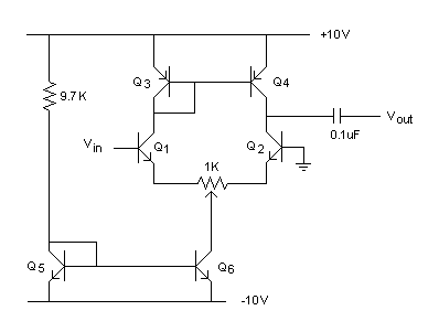
The circuit in Fig. 6.3![[6.3]](/afs/glue.umd.edu/software/tetex/latex2html/latex2html-97.1/icons.gif/cross_ref_motif.gif) shows an emitter resistor between Q1 and Q2.
Usually we add a potentiometer RE at the emitters of Q1 and Q2 for
matching purpose. By adjusting the 1K pot, we can achieve matching between
Q1 and Q2.
shows an emitter resistor between Q1 and Q2.
Usually we add a potentiometer RE at the emitters of Q1 and Q2 for
matching purpose. By adjusting the 1K pot, we can achieve matching between
Q1 and Q2.
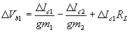
The effect this resistor has on the gain can be seen by realizing that the output configuration has not changed, and looking at the input. Applying KVL at the input loop gives

 .We then find that
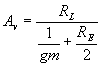
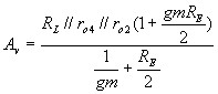
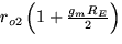 .
This can be shown
with small signal equivalent circuits.
.
This can be shown
with small signal equivalent circuits.