


The circuit in Fig. 6.4 ![[6.4]](/afs/glue.umd.edu/software/tetex/latex2html/latex2html-97.1/icons.gif/cross_ref_motif.gif) represents a realistic operational amplifier.
The circuit is easily understood if it is broken up into is constituent
stages.
represents a realistic operational amplifier.
The circuit is easily understood if it is broken up into is constituent
stages.
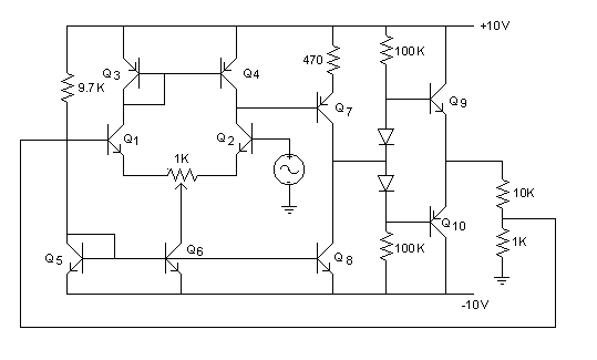
Stage 1 is a difference amplifier. Q1 and Q2 form the emitter coupled pair of the diff amp. Q3 and Q4 form its active load. Q5 and Q6 form a current source which provides bias current.
Stage 2 is a common emitter amp. Q7 (PNP) forms the amplifying BJT, while Q8 is the active load for Q7.
Stage 3 is a push-pull (complementary symmetry) output stage. It is composed of Q9 and Q10, and the diodes.