Project: System-Level Design of a 4-Way Traffic Intersection
Students: Saini Yang and Masoud Hamedi.
Faculty Advisor: Mark Austin.
Date: Spring Semester, 2002.
TABLE OF CONTENTS
-
Problem Statement
Purpose : Setup problem.
Topics : Terminology; sample intersection; system framework and boundary.
-
Goals, Scenarios, and User Requirements
Purpose : Create system requirements.
Topics : Goals and scenarios;
initial use cases and activity diagrams;
system-level requirements;
use-case/task interaction matrices;
traceability.
-
Simplified Models of System Behavior
Purpose : Explain behavior for overall system and sub-system elements.
Topics : Typical behavior for driving activities; sequencing of the traffic lights.
-
Simplified Models of System Structure
Purpose : Explain overall system structure.
Topics : Develop class hierarchy diagram for serialized intersection system.
-
Creating the Logical Design
Purpose : Develop those elements of the problem that are logical in nature.
Topics : Signal timing and signal phasing;
-
Evaluation and Ranking of System-Level Design Alternatives
Purpose : Preliminary evaluation of design alternatives based on timing requirements.
Topics : Use AHP method to compare and rank several design alternatives.
-
Creating the Physical Design
Purpose : Create framework for evaluation of physical design alternatives.
Topics : Models for traffic demand;
measures of effectivenss for traffic throughput;
synthesis of design alternatives (control system and roadway);
performance assessment.
-
Conclusions and Future Work
-
References and Web Resources
Problem Statement
![[Traffic Intersection]](project-traffic-intersection/traffic-fig1.gif)
This document is a work in progress!
The purpose of this case study is to develop a series of
systems model for traffic passing through a 4-way intersection.
We want to explore and understand the extent to which this
problem can be cast in a systems engineering framework -- use cases,
requirements, models of system behavior, system structure,
traceability, and evaluation, ranking and trade-off of
system-level design concerns.
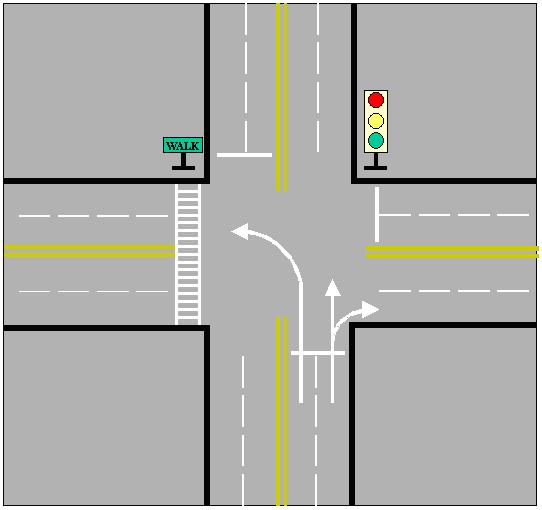
We design an object-oriented model of
cars passing through a 4-way intersection controled by traffic lights.
The adjacent figure shows the layout of road lanes,
queues of cars and traffic lights.
The object model should capture the relationship among the various
components in the problem (i.e., the system structure)
and the behaviors that can be simulated (i.e., the system behavior).
To keep the complexity of development in check,
we will assume that arrangement of traffic lights
and road lanes is fixed, as shown in the adjacent figure,
and that the lights switch from red to
green to amber in a regular repetitive pattern.
Moreover, we assume that driver behavior is constrained by
the road rules (keep this part really simple) and the
desire to avoid vehicle collisions.
The case study will evolve as follows:
-
We will develop a use-case model for traffic behavior at the interesection.
The key steps involve identification of:
(1) the actors and system boundaries,
(2) the use cases,
(3) information flows between the actors and the use cases, and
(3) potential dependencies among the use cases.
-
Develop one or more class hierarchies for this problem,
and indicate how they will communicate.
My suggestion is that you create one class hierarchy for
the intersection and traffic lights, and a
second hierarchy for the vehicle(s) and driver(s).
-
Develop one or more functional flow block diagrams (FFBDs) for
the behavior of cars arriving at the intersection.
-
What is the connection between your class hierarchy(s) and FFBDs?
-
Demonstrate by example how your class hierarchy can be modified
and reused for a slightly different scenario.
Terminology
Terminologies are the first thing we should define before start the project.
Because of the complexity of the intersection control system, terms can
bring us better understanding of the properties.
-
Cycle: one complete sequence of signal indications
-
Phase: part of a cycle allocated to any combination of traffic
movements receiving the right of way simultaneously during one or more intervals.
-
Conflict points: the potential points in a cycle that is possible to make collision.
-
Level of Service: is defined in terms of average stopped
delay per vehicle for signalized intersection.
-
Queue: the total number of vehicle waiting at the intersection
A Sample Intersection
When considering about an intersection, we should consider the following
subsystems:
-
Control system: the control design subsystem, the facility subsystem,
and the signal control subsystems.
-
User system: includes pedestrians, drivers, and traffic engineers.
-
Physical intersection: the geometric information, pavement information
and the traffic information.
To design the systems model for traffic passing through a 4-way
intersection, the core in this project is how to design the control system
so that the drivers and pedestrians can perceive precise and reliable
information, with maximized system capacity and safety.
Since this project is addressed on the logical design, it?s necessary to
clarify the response system between road user and control system and the
design concerns of control system. There are 7 kinds of basic control system
for an intersection.
     i)    No control
    ii)    Guide signing only
   iii)    Guide and warning signing
    iv)    Yield control
     v)    Stop Control
    vi)    Signalization
   vii)    Police officer
Considering the real world situation, we only discuss four cases in our
system.
-
No control.
Here traffic is controled by "rules of the road" alone.
-
Stop control.
Stop sign is needed in one/both direction; the vehicle
will pass according their arriving sequence, first in first out.
-
Stop control.
Stop sign is needed in one/both direction; the vehicle
-
Yield control.
Yield sign is needed in minor direction, no control in
major direction. Cars proceed with caution.
-
Signal control.
Signals are needed. For each direction, signal cycle
and signal phase design is based on the traffic information.
System Framework and Boundary
The traffic intersection system can be conveniently
thought of as the composition of three loosely coupled systems.
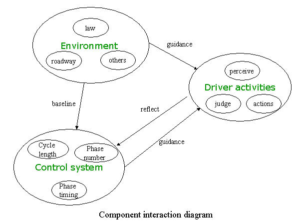
Figure 1. Interaction diagram for the component sub-systems
The sub-systems are:
-
Environment.
The environment covers the world within which the driver must operate (i.e.,
the roadway, rules-of-the-road, and traffic demand).
Driver activities are constrained by each of these entities.
-
Control System.
Here we will simply assume that the intersection is controled by lights (but,
of course, other control strategies also are possible).
The environmental conditions provide a baseline for a suitable
traffic control system design.
In turn, the control system determines the
strategy that will be imposed on traffic control.
-
Driver Activities.
Drivers need to get to their destination without causing an accident.
This requires an "awareness" of other traffic and events relevant to driving,
and an ability to make "judgements" and "take actions"
that will implement driving decisions.
Drivers receive guidance on appropriate courses of
action from the "control system."
On the surface of it, this problem looks really simple.
But it isn't -- writing a behavior diagrams to cover every
possible scenario would be too much work!
This framework also suggests that at the intersection level,
the problem components -- driver activities; interaction with the
other traffic and the control system -- might be modeled as a
network of loosely coupled finite state machines.
System-level modeling parameters would include:
(1) traffic demand; and (2) suitable metrics for traffic throughput.
Goals, Scenarios, and User Requirements
Goals and Scenarios
Goals 1.
The traffic intersection functionality must allow drivers to
pass through the intersection safely.
-
Scenario 1.1:
To the extent possible, the setting of phases should eliminate
the conflict points.
-
The straight traffics in orthogonal direction can't pass the intersection together.
-
The left turn traffic can't pass the intersection at the same time
with the straight traffic in opposing direction.
-
Scenario 1.2:
The time setting of each phase should be reasonable.
-
The setting of green phase length must be long enough for a single
vehicle cross the intersection from static status.
-
The setting of red phase length must be long enough for a single
vehicle in opposite vehicle cross the intersection from static status.
-
The setting of yellow phase length must be long enough for an
approaching vehicle to notice.
-
The setting of pedestrian light length must be long enough for a
senior person to cross the intersection.
-
Scenario 1.3:
The driver must perceive the traffic before action
-
The driver should check the traffic on the same direction.
-
The driver should check the traffic on the opposite direction.
-
The driver should check the traffic on the orthogonal direction.
-
The driver should check the traffic light.
-
The driver should check the pedestrians.
-
Scenario 1.4:
The pedestrian must perceive the traffic before action.
-
The pedestrian should check the traffic light.
-
The pedestrian should check the traffic on orthogonal direction.
-
The pedestrian should check the right turn traffic on same direction.
-
The pedestrian should check the left turn traffic on opposite direction.
Goals 2.
The system must be efficient.
-
Scenario 2.1:
The timing for each phase should be long enough for
cleaning the queue.
-
Scenario 2.2:
The length of a cycle should inside a proper range.
-
Scenario 2.3:
The computed capability should be optimal.
Goals 3.
The system must be economic.
-
Scenario 3.1:
The setting of phase should be compatible with the traffic volume.
-
Scenario 3.2:
The setting of traffic light should be compatible with traffic volume.
-
Scenario 3.3:
The sign system should be compatible with the traffic volume.
Goals 4.
The system must be compatible with traffic law.
-
Scenario 4.1:
The control design should according to the current traffic law.
-
Scenario 4.2:
The users should be aware of the traffic law.
-
The driver should be aware of the traffic law.
-
The pedestrian should be aware of the traffic law.
-
Scenario 4.3:
The sign design should according to the current traffic law.
Goals 5.
The system must be feasible.
-
Scenario 5.1:
The control design should be compatible with the sign system.
-
Scenario 5.2:
The control design should be compatible with the road geometries.
-
Scenario 5.3:
The LOS of the designed intersection can?t below grade f.
Use Cases
The Actors and System Boundaries
Recall that an actor is anything that interfaces with the system externally.
Assuming that the system structure is composed of
the traffic interesection together with the traffic lights,
then the actors for our system are:
Actor (1) : Car/Driver
Here we are simplifying the problem by ignoring the presence of pedestrians.
Another valid viewpoint is that traffic flow through the intersection
simply needs to be controlled, in which case, the traffic lights
can become a second actor that we will simply call:
Actor (2) : Signal System
Under normal working operations, the traffic lights will fullfil the
role of signal system. However, should the signal system fail (e.g., due
to a lightening storm), then control of traffic flow might be
handled by ``rules of the road'' for an uncontrolled intersection,
or perhaps a policeman.

Identify Actors
-
Drivers
-
Pedestrians
-
Signal System
-
Physical Intersection/roadway
-
Laws
Define Users
User 1: Pedestrians
Requirements:
-
Safety: when the pedestrian is crossing the street, no car
-
Perceivable: the information of when to walk and when to stop is
perceivable to the pedestrian.
-
Comfortable: the allowable time for walk is long enough to cross
User 2: Driver
Requirements:
-
Safety: the number of conflicting points is as small as possible.
-
Perceivable: the signals are perceivable and clear to the driver.
-
Comfortable: the allowable time for walk is long enough to cross
the street.
User 3: Signal System
Requirements:
-
Safety: the system has the least possibility of traffic accidents.
-
Efficiency: The capacity of the intersection is maximized.
-
Economy: The total investment of this system is minimized.
-
Advanced requirement*:
-
Environmental consideration: air pollution, vibrations pollution, light pollution.
-
Regional consideration: the influence to the up flow traffic and down low traffic.
Initial Use Case Modeling
The use cases represent system goals or system functions.
Since we consider the safety, efficiency and economy of the system, the
behavior of driver drives through an intersection can be divided into 3
parts:
-
Driver's Action: Go straight ahead, turn left or turn right.
-
Driver Activities: Watch the traffic lights, the traffic in other
lanes and the pedestrians, etc.
-
System Functionality: Cycle length and phase setting.
Our initial use case diagram has five actors and nine use cases.
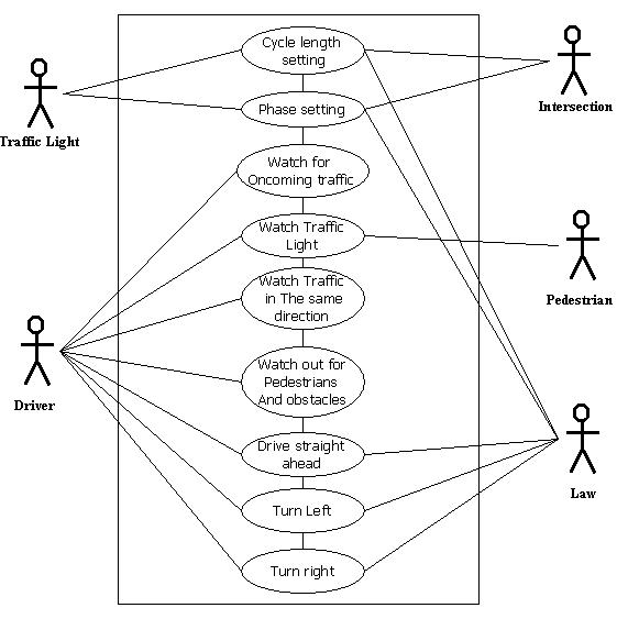
Figure 2. Initial Use Case Diagram
The driver, other traffic, pedestrian and other obstacles, and traffic
lights are all external systems.
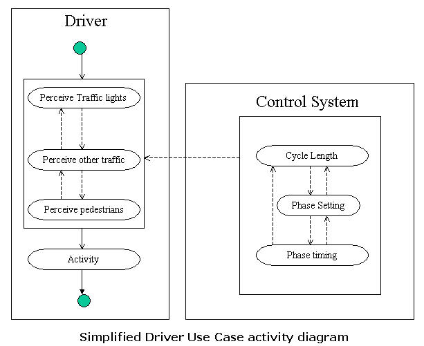
Figure 3. Simplified Driver Use Case/Activity Diagtram
Baseline (Textual) Use Cases
The use cases represent system goals (or system functions).
Generally speaking, drivers want to pass through the
intersection -- going straight ahead, or turning left or right --
without colliding into another car (or pedestrian).
To avoid collisions and obey the road rules,
drivers also need to:
(1) Watch the traffic lights;
(2) Watch traffic travelling in the same direction; and
(3) Watch for oncoming traffic.
To avoid collisions and obey the road rules,
drivers should also watch out for pedestrians and
other unexpected obstacles.
Finally, the purpose of the signaling system is to alternate direction of
allowable traffic flow at reasonable intervals of time.
Functionality of the Traffic Lights
Use Case (1): Cycle length setting.
-
Description.
The cycle length setting should improve the capability of the intersection.
Primary Actor. Roadway, Law.
Pre-conditions.
The roadway geometries and traffic data are known, drivers always follow the traffic law.
Flow of events:
-
Collect daily traffic volume.
-
Limited the cycle length in 50 seconds to 90 seconds according to the daily traffic volume.
Post-conditions. Traffic data is known, and the cycle length is limited.
Use Case (2): Phase setting.
-
Description.
The phase setting should improve the capability of the intersection.
Primary Actor. Roadway, Law.
Pre-conditions.
The roadway geometries and traffic data are known, drivers always follow the traffic law, and the cycle length is known.
Flow of events:
-
Decide the number of signal phases.
-
Decide the time setting for each phase.
Post-conditions.
Traffic cycle length and detailed phase setting are given.
Functionality of a Driver
Use case (3): Watch the traffic lights.
-
Description.
The driver should be able to perceive the traffic light information.
Primary Actor. Driver, signal system.
Pre-conditions.
The traffic signal system is available and stable;
drivers always follow the traffic law.
Flow of events:
-
The traffic lights are perceivable.
-
The driver has correct understanding of the traffic light.
Post-conditions.
The driver is clear about the current signal status and
has enough expectation of the possible change.
Use Case (4): Watch traffic traveling in the same direction.
-
Description.
The phase setting should improve the capability of the intersection.
Primary Actors.
Driver Roadway, Law.
Pre-conditions.
The roadway geometries and traffic data are known;
drivers always follow the traffic law.
Flow of events:
-
Watch the traffic in the same lane.
-
Watch the traffic in the other lanes.
Post-conditions.
Perceive the traffic in the same direction and find a proper
Use Case (5): Watch for oncoming traffic.
-
Description.
The driver should perceive the oncoming traffic before do any proceed action.
Primary Actors.
Driver, Roadway, Law.
Pre-conditions. None.
Flow of events:
-
Watch the oncoming (includes the traffic in orthogonal direction) straight traffic.
-
Watch the oncoming (includes the traffic in orthogonal direction) left-turn traffic.
-
Watch the oncoming (includes the traffic in orthogonal direction) right-turn traffic.
Post-conditions.
The driver has perceived the signal information
Use Case (6): Watch out for pedestrians and other unexpected obstacles.
-
Description.
The driver should try to avoid collisions
with pedestrians and other vehicles.
Primary Actors.
Driver, Pedestrian, Law.
Pre-conditions.
The driver has already perceived the traffic signals and other traffic.
Post-conditions.
The signal information and traffic information are ready.
Use cases 3 through 6 can be represented in a single activity diagram!
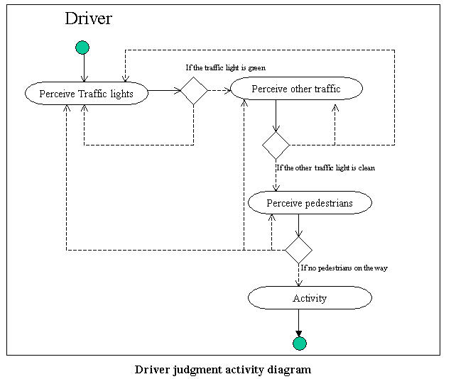
Figure 4. Driver Judgement Activity Diagtram
Use Case (7): Drive straight ahead.
-
Description.
Driver should be able to drive the vehicle straight ahead.
Primary Actors.
Driver, other traffic, law.
Pre-conditions.
The signal information and pedestrians? information is perceived.
Flow of events:
-
Judge if the integrated information allows driving.
-
Execute under the limitation of Law.
Post-conditions.
The driver drives the car pass the intersection

Figure 5. Activity Diagram for Driving Straight through the Intersection
Use Case (8): Turn right.
-
Description.
The phase setting should improve the capability of the intersection.
Primary Actors.
Driver, Roadway, Law.
Pre-conditions.
The traffic signal system is available and stable;
drivers always follow the traffic law,
the driver has perceived the signal
information and traffic information in all direction.
Flow of events:
-
If the traffic light is green and the gap is large enough when there is yield control.
-
Turn right with proper execution.
Post-conditions.
The driver drives the car pass the intersection.
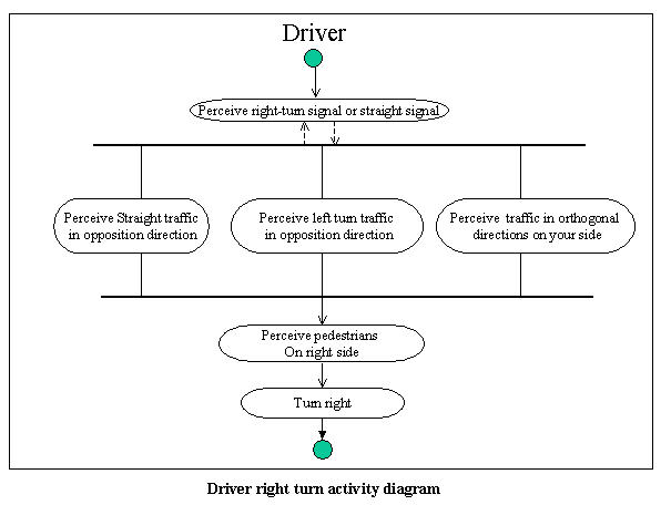
Figure 6. Activity Diagram for Turning Right at the Intersection
Use Case (9): Turn left.
-
Description.
The phase setting should improve the capability of the intersection.
Primary Actors.
Driver, Roadway, Law.
Pre-conditions.
The traffic signal system is available and stable;
drivers always follow the traffic law,
the driver has perceived the signal information
and traffic information in all direction.
Flow of events:
-
If the traffic light is green and the gap is large enough when there is yield control.
-
Turn left with caution.
Post-conditions.
The driver drives the car pass the intersection.
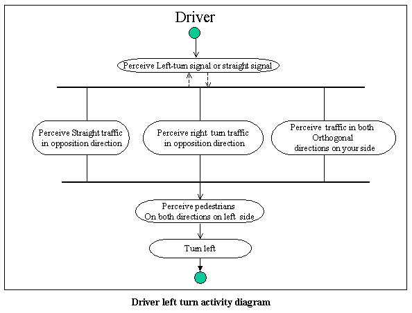
Figure 7. Activity Diagram for Turning Left at the Intersection
Relationships Among Use Cases
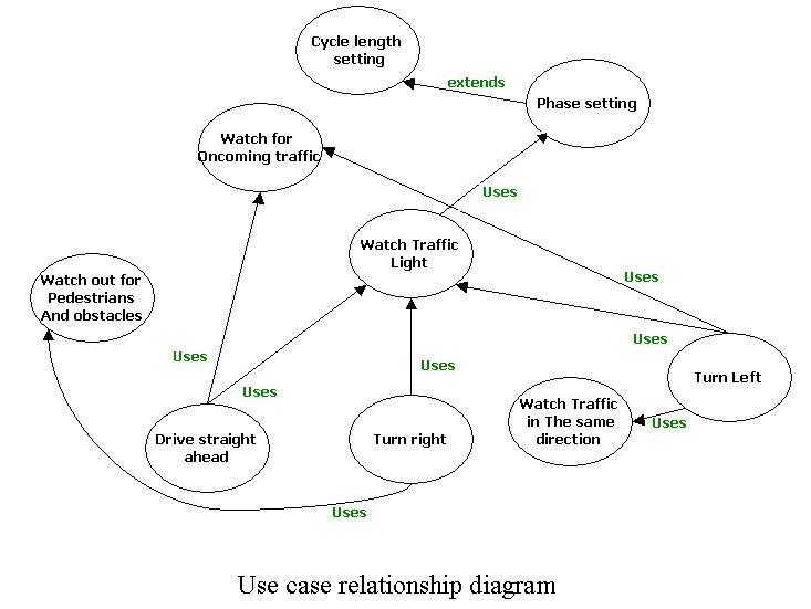
Figure 8. Dependencies Among the Use Cases
Dependencies Among Use Cases.
Use cases 1, 2, and 3 employ indirectly use cases 4, 5 and 6.
For the vast majority of traffic intersections,
operation of the signal system will be unaffected by
the presesence/lack of traffic at the intersection.
For those cases where traffic flow is light,
permissible behavior is governed by ``rules of the road.''
Use Case/Task Interaction Matrix
The following table summarizes the dependecies among use cases.
| *Column Sends. Row receives. |
Use Case
|
| 1 |
2 |
3 |
4 |
5 |
6 |
7 |
8 |
9 |
| Use Case 1. Cycle Length Setting. |
1 |
|
|
|
|
|
|
|
|
| Use Case 2. Phase Setting. |
X |
2 |
|
|
|
|
|
|
|
| Use Case 3. Watch the traffic light. |
|
X |
3 |
|
|
|
|
|
|
| Use Case 4. Watch the traffic light in the same direction. |
|
|
X |
4 |
|
|
|
|
|
| Use Case 5. Watch for oncoming traffic. |
|
|
X |
X |
5 |
|
|
|
|
| Use Case 6. Watch for pedestrians and other unexpected vehicles. |
|
|
X |
|
|
6 |
|
|
|
| Use Case 7. Drive straight ahead. |
|
|
X |
|
|
|
7 |
|
|
| Use Case 8. Turn right. |
|
|
X |
|
|
X |
|
8 |
|
| Use Case 9. Turn left. |
|
|
X |
|
X |
|
|
|
9 |
Table 1. Use Case/Task Interaction Matrix.
Note.
We need to check that the use case/task interaction matrix
is consistent with the "use case relationship diagram".
System Requirements
5.1. Safety Requirements
-
The traffic control system should minimize the likelihood
of collisions within the intersection.
-
Time phasing of the traffic lights should be
reasonable for all directions and pedestrians.
-
Drivers and pedestrians should perceive traffic before action
5.2. Performance Requirements
-
The timing for each phase should be long
enough for cleaning the queue of traffic.
-
The computed capability should be optimal.
5.3. Compatibility Requirements
-
The setting of phase should be compatible with the traffic volume.
-
The setting of traffic light should be compatible with traffic volume.
-
The sign system should be compatible with the traffic volume and law.
-
The control design should according to the current traffic law.
-
The users should be aware of the traffic law.
-
The control design should be compatible with the sign system.
-
The control design should be compatible with the road geometries.
-
The LOS of the designed intersection can't below grade f.
Traceability
The following summarizes the pathway from use cases to scenarios,
to individual requirements.
| Use Case |
Scenario |
Req. No |
Description |
| Cycle length setting |
Scenario 1.1 |
Req 5.1.1 |
Control system should avoid collision in the intersection |
| Req 5.2.2 |
The computed capability should be optimal. |
| Scenario 2.2 |
Req 5.3.2 |
The setting of traffic light should be compatible with traffic volume. |
| Phase setting |
Scenario 1.2 |
Req 5.1.2 |
Time phasing should be reasonable for all directions and pedestrians. |
| Scenario 2.1 |
Req 5.2.1 |
The timing for each phase should be long enough for cleaning the queue. |
| Watch the traffic light |
Scenario 4.2 |
Req 5.1.3 |
Drivers and pedestrians should perceive traffic before action. |
| Req 5.3.5 |
The users should be aware of the traffic law. |
|
Watch traffic traveling in the same direction |
Scenario 4.3 |
Req 5.3.5 |
The users should be aware of the traffic law. |
| Watch for oncoming traffic |
Scenario 1.3 |
Req 2.3.5 |
The users should be aware of the traffic law. |
|
Drive straight ahead/Turn right/Turn left |
Scenario 2.1 |
Req 5.3.2 |
The setting of traffic light should be compatible with traffic volume. |
| Scenario 1.1 |
Req 5.1.1 |
Control system should avoid collision in the intersection. |
| Req 5.1.2 |
Time phasing should be reasonable for all directions and pedestrians. |
Table 2. Traceability from Use Cases to Requirements.
This table shows two effects:
-
Generally, individual use cases are described by multiple scenarios,
which in turn are represented by even more requirements.
-
A single requirement can participate in the implementation
of more than one use case (see, for example, requirement 5.1.1).
During the logical and physical stages of design,
individual requirements will be traced onto elements of
the system behavior and system structure.
Simplified Models of System Behavior
System has the following main subsystems:
-
Controller System
-
Controller Interface (Traffic Light)
-
Intersection
-
User System (Cars and pedestrians)
The overall system behavior is defined by the time-dependent
behavior of the system's loosely coupled
components (i.e., traffic lights; drivers).
Driver Behavior
At a high level of abstraction, the driver behavior can
be encapsulated by a combination of activities.
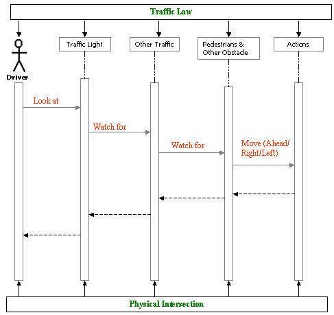
Figure 9. Simplified Model of System Behavior
By "driver action" we simply mean one of:
-
Drive straight ahead. See Figure 5.
-
Turn right. See Figure 6.
-
Turn left. See Figure 7.
Flows of Information
Information flows from the Car/Driver
to the individual use cases for traffic direction (right, left, straight ahead).
Information also flows from use cases 4, 5, and 6 to the Car/Driver.
Information also flows from the signaling system to the use cases
for allowable traffic behavior (turn left or right; straight ahead),
which in turn, is forwarded to the appropriate car/driver.
Traffic Light Control System Behavior.
Behavior of the traffic light control system is defined by
the phasing and cycle of the traffic lights,
as well as provision for abnormal behaviors.
Together, the "phasing and cycle" of the control system
constitute the "signal timing" for the taffic lights.
Signal Phasing
Signal phasing is concerned with the design of the
sequence of traffic light control service, which in turn,
affects movements of both vehicles and pedestrians being
served at a signalized intersection.
Phasing precedes all other signal timing steps.
The objective of phasing is the minimization of
the potential hazards arising from the
conflicts of vehicular and pedestrian movements, while maintaining the
efficiency of flow through the intersection. Typical conflicts are
-
Left turning vehicles conflict with opposing through traffic as well as with pedestrian,
-
Right turning vehicles conflict with pedestrians
Cycle Length
Then the cycle length is estimated and green times are
allocated to each phase according to the
relative magnitude of traffic flows served in each phase.
Cycle lengths should be designed to avoid substantial delays,
traffic congestion within the intersection,
and the endangerment of pedestrians.
Two possibilities for cycling are:
-
US.
Green, amber, red, green, amber, red, .... and so forth.
-
Scandinavia (and some other European countries).
Green, amber, red, amber, green, amber, red, .... and so forth.
In countries where gasoline is expensive (i.e., most of Europe),
some drivers turn their cars off at a red light. The amber light
is a warning to turn their vehicles back on.
Certain constraints must be checked to ensure the safe and efficient
processing of vehicles and pedestrians at an intersection.
Environment Behavior.
Even over extended periods of time the "rules and regulations"
for driving are likely to remain constant.
As the traffic demand increases (due, perhaps, to an increase
in population), roadways will be enhanced to better control traffic flow.
This study ignores these long-term effect.
Attributes of System Behavior/Performance
-
Traffic Light Control Systems
-
Signal phasing and cycling.
-
Timing for each phase.
-
Driver Activities
-
Ability to avoid accidents.
-
Mean and maximum waiting times to pass through the intersedion.
Traceability of Requirements to Attributes of System Behavior
Insert material soon .....
Simplified Models of System Structure
The signalized intersection system includes four main subsystems:
traffic lights, environment, driver. However, the whole system can only work under the
coordination of user, environment and facilities.
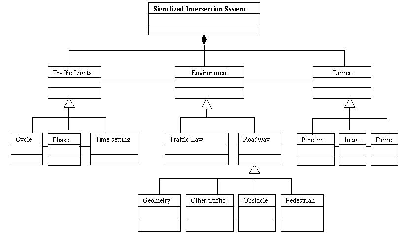
Figure 10. Simplified Model of System Structure
The attributes for each part of the class hierarchy will be determined,
in part, by mappings of system behavior onto system structure.
Attributes of System Structure
-
Traffic Light Attributes
No of traffic light signal boxes
No of lights (red, green, amber, turning) on each signal box
Orientation of traffic lights
-
Cycle Attributes
"US" or "European" cycling?
-
Phase Attributes
No of "phases" in the traffic movement -- usually this will be 2, 3 or 4.
-
Time Setting Attributes
Timing for each phase.
Traffic light geometry
Energy consumption
Mean time-to-failure for the lights
Maintenance costs
-
Environmental Attributes
-
Traffic Law Attributes
-
Roadway Attributes
-
No of lanes
-
No of turning lanes
-
Width of the lanes
-
Length of the turning lanes -- this affects likelihood of traffic backup.
-
Driver Attributes
Age, License
Reaction time
-
Perception Attributes
-
Visual and hearing acuity
-
Judgement Attributes
-
Mental stability
-
Alchol level in bloodstream
-
Driving Mechanisms
-
Average waiting time at the intersection.
-
Maximum waiting time at the intersection.
Points to note are as follows:
-
Collectively, the elements of the "system structure" define the
initial cost of the traffic light control system,
and cost of operation and maintenance.
-
In California, Caltrans is experimenting with LED traffic signals as
a replacement for the traditional incondescent traffic lights (Piper, 2002).
-
Wider traffic lanes reduce the likelihood of vehicle interference in adjacent lanes.
They also make drivers feel more comfortable.
Ideal conditions require that lanes be at least 12 ft wide (Papacostas, pg. 173).
-
Driver reaction time is related to: age, mental condition, alchol/drug use.
fatigue, sleep deprevation, emotional condition.
-
Visual acuity refers to the sharpness with which a person can see an abject.
Factors affecting acuity include:
(1) contrast and brightness of the object,
(2) the level of illumination, and
(3) the relative motion between the observer and object.
Traceability of Requirements to Attributes of System Structure
Insert material soon .....
Creating the Logical Design
Synthesis (Generation) of Design Alternatives
Increasing the number of phases in the control system operation
promotes safety but hinders efficiency
because it results in increasing delays. Delay increases because
-
Start-up lost times,
-
Phase change intervals increase
-
Minimum phase duration requirements have to be met
The following figure shows two, three and four phase signal operation
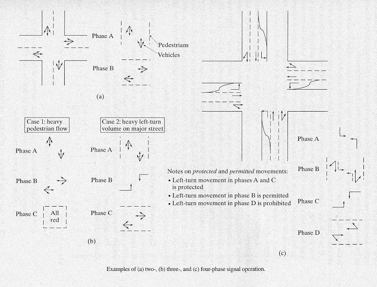
Figure 11. Examples of Two, Three, and Four-Phase Signal
Operation (Papacostas, pg. 202)
The attributes of two, three and four-phase signal operation are as follows:
-
Two-Phase Signal Operation
This mode of operation is appropriate for intersections with
low pedestrian volumes, low-to-moderate turning volumes,
and vehicle arrivals with an adequate number of sufficiently
long gaps that permit left-turning vehicles to be served
within the "green time" allocated to the phase (Papacostas, pg. 202).
-
Three-Phase Signal Operation
The three-phase operation is appropriate when one of the
conditions for two-phase operation is violated. i.e.,
high volume of pedestrians;
high left-turning volume on one of the two intersecting streets.
-
Four-Phase Signal Operation
A four-phase operation is preferred when there are heavy volumes of
left-turning traffic on both intersecting streets,
Actuated controllers are able to modify the cycle length as well
as the durations of of green to better serve the actual demand.
The flexibility of these systems results in more efficient
service of traffic and and in the minimization of delays. Actuated
controllers perform best at isolated locations and during off-peak times.
Example of Four-Phase Signal Behavior
The following figure illustrates the operation of a four-phase scheme
under actuated control.
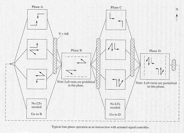
Figure 12. Typical Four-Phase Operation of an Interesection
with Actuated Signal Control (Papacostas, pg. 205)
Traceability -- Pathways of Behavior in the Logical Design
Insert material soon .....
Evaluation and Ranking of System Design Alternatives
Measures of Effectiveness
According to the analysis of system goals we can define our measure of
system effectives in the following aspects:
-
Safety: the total accident per year, the accident related cost per
year, the number of deaths caused by the accident per year?
-
Capacity: level of service of the intersection, the average delay per
vehicle, the peak-hour capacity,?
-
Economy: the construction cost, maintenance cost, etc.
-
Other considerations: noise pollution, sound pollution, vibration
pollution, land use impact,?
The effectiveness measures are listed in the following table.
| |
Goals |
Weight |
Measures |
Weight |
Sub-measures |
Weight |
| System |
Safety |
0.3 |
Death rate |
0.3 |
|
|
| Accident rate |
0.4 |
|
|
| Accident rate cost |
0.4 |
|
|
| Capability |
0.3 |
Level of service |
0.4 |
|
|
| Average delay |
0.4 |
|
|
| Peak hour capacity |
0.2 |
|
|
| Economy |
0.2 |
Construction cost |
0.4 |
|
|
| Maintenance cost |
0.4 |
|
|
| Other |
0.2 |
Environmental Impact |
0.5 |
Sound |
0.4 |
| Polution |
| Light Polution |
0.3 |
| Air Polution |
0.3 |
| Land Use Impact |
0.5 |
|
|
Table 3. Measures of Effectiveness and Weightings for System Goals
The difficulty in the trade-off process is that the measures are in different
scales, and it’s difficult to unify them to one unit so that we can find the
optimal alternative easily. However, we can use the concept of “weight” to
compare the importance of these measures. Here, we list the proposed weight for
each measure, but a more reasonable and precise decision of weights need further
discussion
Ranking Design Alternatives
With the consideration of available budgets and technician, even the
possible land use constraints. The best alternatives should be some design
plan with the maximum evaluation value.
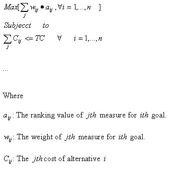
We introduce a ranking system in this evaluation process, which is described
as below:
-
Assume there are n alternatives.
-
Compare the value of one measure of each alternative, i=1,..n , the
alternative with the best measurement value gets n-1 , the second best
gets n-2 , ? the worst get 0 .
-
Get the weighted summation of the ranking values for each alternative.
-
Pickup the alternative with the largest weighted summation value,
subject to the budget constraints and technology constraints.
Then the formulation can be:
However, with concern about safety, we should apply
some ‘minmax’ criterion into the trade-off
procedure, e.g. suppose for each traffic condition
the total ranking result is shown as the following table.
| |
Heavy Traffic |
Medium Traffic |
Light Traffic |
| Alternative 1 |
1 |
2 |
3 |
| Alternative 2 |
3 |
1 |
2 |
| Alternative 3 |
4 |
3 |
1 |
| Alternative 4 |
2 |
4 |
4 |
Then if we apply the "minmax" criterion here, we will choose alternative
1 or alternative under the assumption that all these 3 events happen with same
probability.
If we assign the possibility as below:
| Event |
Heavy Traffic |
Medium Traffic |
Light Traffic |
| Probability |
0.3 |
0.5 |
0.2 |
Then we should choose alternative 1,
because it has less possibility to be the worse case.
If we apply maxmax, then we should choose alternative 2.
Creating the Physical Design
Model for Traffic Demand
The key steps are:
-
Identification of the overall traffic demand.
-
Assignment of traffic volumes to lanes (i.e., reflecting the
percentage of cars that will turn left, turn right, and
drive straight ahead).
Measures of Effectiveness for Traffic Throughput
-
What is the vehicle throughput per hour in each lane?
Synthesis of Design Alternatives (Traffic Control Systems and Roadway)
-
No lanes. Phases and cycling of the traffic light.
Capacity and Performance Assessment for Design Alternatives
-
Insert material soon .....
Conclusions and Future Work
A traffic system is a typical "system of system?" [Image].
In this project, we can learn how to planning and analyze a complex
system with the systematic, integrated process,
find the inner relation between each components and design the system.
In a signal control intersection, the actors are far more than the driver
himself, depends on the degree of complexity, much more actors interact with
the system externally, such as signal system, pedestrians, other traffic,
even roadway law and vehicle itself.
The decision of actors depends on the scale and depth of the system design.
However, after fix the scale and depth of the problem, it?s become much
easier to write down the goals and scenarios, user cases and system
behavior, however, with the consideration of accordance all the time.
Comparatively, the logical design is the most difficult part of this
project. It shows the core of our understanding of the system design, and a
clear and brief explanation is difficult to achieve. Also, trade-off system
is another key point that is difficult to fulfill because of the lack of
quantitative measures.
The system we designed actually is simplified to some extend. More extension
can be done with the consideration of control method choice, signal setting
details with system behavior, more specifications on user cases, etc.
We are glad to see our improvement in the system design of signalized
intersection, but, without doubt, there?s a lot of space for us to explore
for a more precise and more concrete system design.
References and Web Resources
Systems Engineering and Traffic Engineering
-
Austin M.A. and Frankpitt B.A., “System
Engineering Principles: Lecture notes for ENSE 621 and ENPM 641”, 1998.
-
Austin M.A., “System Engineering
Requirements, Design and Trade-off Analysis: Lecture notes for ENSE 622 and
ENPM 642”, 2002.
-
Berry D.S., "Notes on Traffic Engineering," Unpublished.
Northwestern University, Evanston, Ill, 1978.
-
William R. McShane, Roger P. Roess, “Traffic Engineering”, Prentice Hall, 1990.
-
Papacostas C.S., Prevedouros P.D., "Transportation Engineering &
Planning", Prentice Hall, 2001.
-
Traffic Control Systems Handbook", US Department of Transportation, Federal
Highway Administration, 1996.
Traffic Light Design
-
Piper S., "LED Traffic Signals get the Green Light,"
Forefront, College of Engineering, University of California, Berkeley,
Fall Semester 2002, pp. 6.
-
Lamb A., "Simplicity in the design of a Traffic Light Controller,"
See http:.....
Developed by Saini Yang and Masoud Hamedi, May 2002.
Modified by Mark Austin, July-November 2002
Copyright © 2002, Saini Yang, Masoud Hamedi, and Mark Austin. All rights reserved.