 Finite Element Analysis of a Two-Span Highway Bridge
 Finite Element Analysis of a Two-Span Highway Bridge
[ Problem Description ]
[ Description of Highway Bridge ]
[ Finite Element Model ]
[ Finite Element Analysis (Dead Loads Alone) ]
[ Moving Live Loads ]
[ Input and Output Files ]
In this example, we will use ALADDIN for the three-dimensional finite element analysis of a two-span highway bridge structure. We will compute:
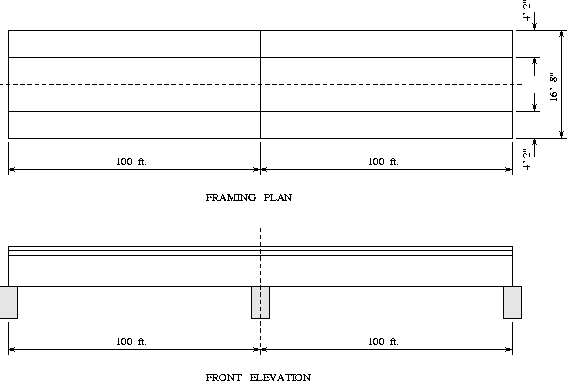
A plan and front elevation view of the highway bridge system is shown in Figures 1 and 2.


The bridge has two spans, each 100 ft long. The width of the bridge is 16 ft - 8 inches. The left-hand side of the bridge is a hinged support, and the right-hand side, is supported on a roller.
The bridge is constructed from one steel and one concrete material type. The structural steel has Fy = 50 ksi, Poisson's ratio v = 0.3, and E = 29,000 ksi. For the concrete slab, fc = 4000 psi, Poisson's ratio v = 0.3, Ec = 3625 ksi, and unit weight = 150 pcf. The W36x170 steel section has the following properties -- d = 36.17 in, bf = 12.03 in, tf = 1.1 in, tw = 0.68 in, and weight = 170 lbf/ft. The concrete slab has thickness 7 in.
Figures 3 and 4 are plan and cross section views of the finite element mesh, respectively.


The finite element model has 399 nodes and 440 shell elements. After the boundary conditions are applied, the model has 2374 d.o.f.
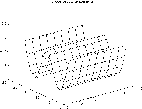
Figure 5 is a MATLAB plot of the computed bridge deck deflections due to dead loads alone.

As expected, the vertical deck deflections are symmetric about the center support, and the axis of symmetry in the bridge's longitudinal direction.
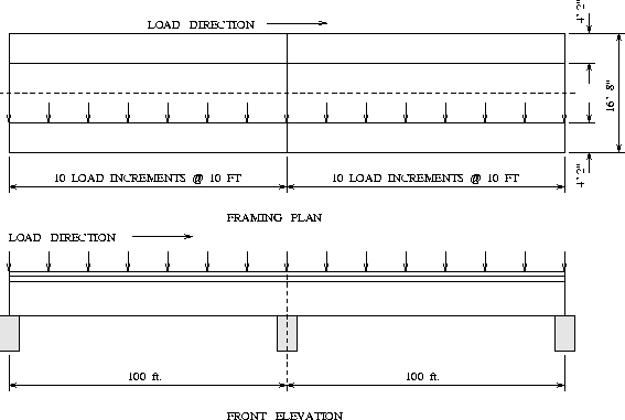
Figure 6 shows the plan and elevation views of the bridge with the 1000 kip moving live load.

The influence diagram is computed by systematically moving the point load along finite element nodes over-lying the outer bridge girder.
/* [d] : Compute Influence Lines for Moving Live Loads */

   print "\n*** STATIC ANALYSIS PROBLEM \n\n";

   Fx = 0 lbf;    Fy = 0 lbf;    Fz = -1000.0 kips;
   Mx = 0 lbf*in; My = 0 lbf*in; Mz = 0 lbf*in;

   nodeno1 = 97;
   nodeno2 = 103;
   step   = div_L*2+1;
   print "node no 1 =",nodeno1,"\n";
   print "node no 2 =",nodeno2,"\n";
   print "Fz        =",Fz,"\n";
   print "step      =",step,"\n";

   influ_line1 = Zero([ step , 1 ]);  /* array for influence line 1 */
   influ_line2 = Zero([ step , 1 ]);  /* array for influence line 2 */

   load_node = 2;
   lu = Decompose (stiff);
   for( i=1 ; i<=step ; i=i+1 ) {
        NodeLoad( load_node, [Fx,Fy,Fz,Mx,My,Mz] );

        eload = ExternalLoad();
        displ = LUDecomposition( stiff, eload );

        node_displ_1 = GetDispl( [nodeno1], displ );
        node_displ_2 = GetDispl( [nodeno2], displ );

        influ_line1[i][1] = node_displ_1[1][3];
        influ_line2[i][1] = node_displ_2[1][3];

        NodeLoad( load_node, [-Fx,-Fy,-Fz,-Mx,-My,-Mz] );
        load_node = load_node + nodes_per_section;
   }

   PrintMatrix(influ_line1);
   PrintMatrix(influ_line2);
You should notice that our moving load analysis begins with the decomposition of the stiffness matrix into a product of lower and upper triangular forms -- this step requires O(n^3) computational work. Then the bridge deck displacements are computed with repeated applications of forward and backward substitution. Each set of displacements is obtained with only O(n^2) computational work.
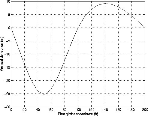
The influence lines of mid-span displacement are stored in the arrays influ_line1 and influ_line2, one for each of the bridge girders.

Figure 9 is the influence line of midspan displacement under the girder along which the point live load is moving.